Lesson:
Electricity
Question 1
A cell, a
resistor, a key and ammeter are arranged as shown in the circuit diagrams figure
given below. The current recorded in the ammeter will be:
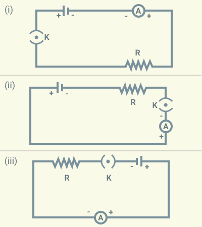
(a) Maximum in (i)
(b) Maximum in
(ii)
(c) Maximum in
(iii)
(d)
The same in all the cases
Solution:
b
Question 2
In the following
circuits, heat produced in the resistor or combination of resistors connected
to a 12 V battery will be:
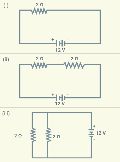
(a) Same in all
the cases
(b) Minimum in
case (i)
(c) Maximum in
case (ii)
(d) Maximum in case (iii)
Solution:
a
Question 3
Electrical resistivity of a given metallic
wire depends upon
(a) Its length
(b) Its thickness
(c) Its shape
(d)
Nature of the material
Solution:
d
Question 4
A current of 1 A
is drawn by a filament of an electric bulb. Number of electrons passing through
a cross section of the filament in 16 seconds would be roughly:
(a)
(b)
(c)
(d)
Solution:
a
Question 5
In the following
circuits, identify the one in which the electrical components have been
properly connected.
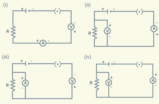
(a) (i)
(b) (ii)
(c) (iii)
(d) (iv)
Solution:
b
Question 6
What is the
maximum resistance which can be made using five resistors each of ?
(a)
(b) 10 Ω
(c)
5 Ω
(d)
1 Ω
Solution:
d
Question 7
What is the
minimum resistance which can be made using five resistors each of ?
(a)
(b)
(c)
(d)
25 Ω
Solution:
b
Question 8
In the given below
figure, the proper representation of series combination of cells obtaining
maximum potential is:
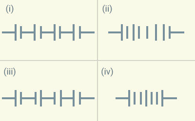
(a) (i)
(b) (ii)
(c) (iii)
(d) (iv)
Solution:
a
Question 9
Which
of the following represents voltage?
(a)
(b)
(c)
(d)
Solution:
a
Question 10
A cylindrical
conductor of length l and uniform area of cross-section A has
resistance R. Another conductor of length 2l and resistance R of
the same material has area of cross section:
(a)
(b)
(c) 2 A
(d) 3 A
Solution:
c
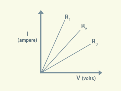
Question 11
A student carries
out an experiment and plots the V-I graph of three samples of nichrome wire
with resistances R1, R2 and R3
respectively. Which of the following is true?
(a)
(b)
(c)
(d)
Solution:
c
Question 12
If the current I
through a resistor is increased by100% (assume that temperature remains unchanged),
the increase in power dissipated will be:
(a) 100 %
(b) 200 %
(c)
300 %
(d)
400 %
Solution:
c
Question 13
The
resistivity does not change if:
(a) The material
is changed
(b) The
temperature is changed
(c) The shape of
the resistor is changed
(d)
Both material and temperature are changed
Solution:
c
Question 14
In an electrical
circuit three incandescent bulbs A, B and C of rating 40 W, 60 W and 100 W
respectively are connected in parallel to an electric source. Which of the
following is likely to happen regarding their brightness?
(a) Brightness of
all the bulbs will be the same
(b) Brightness of
bulb A will be the maximum
(c) Brightness of
bulb B will be more than that of A
(d) Brightness of
bulb C will be less than that of B
Solution:
c
Question 15
In an electrical
circuit two resistors of 2 Ω and 4 Ω respectively are connected in series to a
6 V battery. The heat dissipated by the 4 Ω resistor in 5 s will be:
(a) 5 J
(b) 10 J
(c) 20 J
(d) 30 J
Solution:
c
Question 16
An electric kettle
consumes 1 kW of electric power when operated at 220 V. A fuse wire of what
rating must be used for it?
(a) 1 A
(b) 2 A
(c) 4 A
(d) 5 A
Solution:
d
Question 17
Two resistors of
resistance 2 Ω and 4 Ω when connected to a battery will have:
(a) Same current
flowing through them when connected in parallel
(b) Same current
flowing through them when connected in series
(c) Same potential
difference across them when connected in series
(d) Different
potential difference across them when connected in parallel
Solution:
b
Question 18
Unit
of electric power may also be expressed as:
(a) Volt ampere
(b) Kilowatt hour
(c) Watt second
(d)
Joule second
Solution:
a
Short Answer Questions
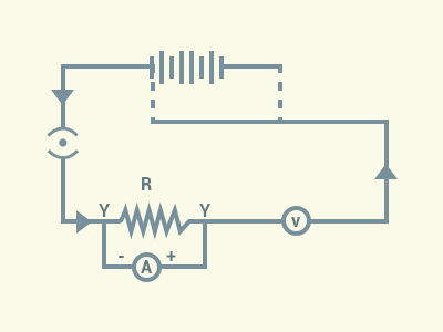
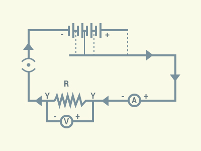
Question 19
A child has drawn
the electric circuit to study Ohm’s law as shown in given below figure. His
teacher told that the circuit diagram needs correction. Study the circuit
diagram and redraw it after making all corrections.
Solution:
Question 20
Three 2 Ω
resistors, A, B and C, are connected as shown in the following figure. Each of
them dissipates energy and can withstand a maximum power of 18 W without
melting.
Find the maximum
current that can flow through the three resistors?
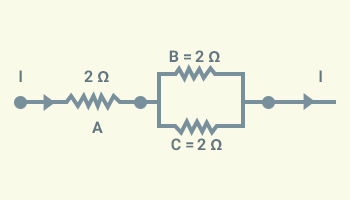
Solution:
Maximum current
through resistor A
Given that the resistance
of each of the resistors are 2 Ω
each and maximum power the resistors can withstand is 18 W.
The power dissipated is
given by, .
The maximum current that the resistor A can withstand
Since B and C are connected in parallel, the 3A of current that passes
through the resistor A splits and passes through the resistor B and C equally. Thus,
the maximum current through resistors B and C each,
.
Question 21
Should the
resistance of an ammeter be low or high? Give reason.
Solution:
An
ammeter measures the current passing through a circuit. Ideally, an ammeter
should not have any resistance as resistance of the ammeter reduces the amount
of current passing through it and therefore the actual amount of current
passing through a circuit cannot be determined. However, in practice, every
ammeter will have some amount of resistance at least. Therefore, the best
option would be to have an ammeter with minimum possible resistance.
Question 22
Draw a circuit
diagram of an electric circuit containing a cell, a key, an ammeter, a resistor
of 2 Ω in series with a combination of two resistors (4 Ω each) in parallel and
a voltmeter across the parallel combination. Will the potential difference
across the 2 Ω resistor be the same as that across the parallel combination of
4 Ω resistors? Give reason.
Solution:
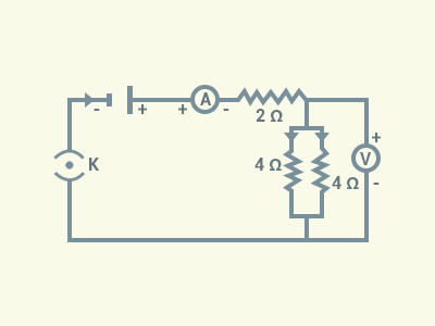
When
two resistors are connected in series, the potential difference across resistors
will be equal only if the resistance of the resistors are equal.
The
combined resistance of two resistors connected in parallel is 2 Ω.
Thus, the potential difference
across the 2 Ω resistor will be the same as that across the parallel
combination of two 4 Ω resistors.
Question 23
How
does use of a fuse wire protect electrical appliances?
Solution:
A fuse consists of a piece of wire made up of an alloy or metal of an
appropriate melting point. When the current higher than a specified value flows
through a wire, the temperature of the fuse wire increases; leading to the
melting and breakage of the circuit.
Thus, a fuse stops the flow of any unduly high electric current in a circuit.
This helps in protecting electrical appliances from damages.
Question 24
What is electrical
resistivity? In a series electrical circuit comprising a resistor made up of a
metallic wire, the ammeter reads 5 A. The reading of the ammeter decreases to
half when the length of the wire is doubled. Why?
Solution:
Resistivity is a measure of resistance offered to an electric current by
a conducting substance.
Resistance of a conductor is given by the relation,
where l is the length, A is
the area of cross-section of the wire and is resistivity of the wire.
In simple words, the more is the resistivity of a substance, the more is
its resistance.
The SI unit of
electrical resistivity is ohm-metre (Ω.m).
When the length
of the wire is doubled, the resistance offered by the wire also doubles. This
reduces the amount of current by half. This can be understood from the equation
. Here I
is the current and R is the
resistance in a circuit across a voltage of V.
Question 25
What is the
commercial unit of electrical energy? Represent it in terms of joules.
Solution:
The commercial unit of electrical energy is
kWh.
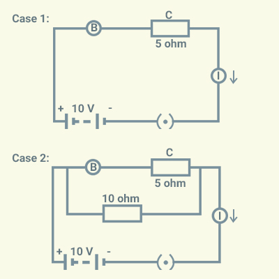
Question 26
A current of 1
ampere flows in a series circuit containing an electric lamp and a conductor of
5 Ω when connected to a 10 V battery. Calculate the resistance of the electric
lamp.
Now if a
resistance of 10 Ω is connected in parallel with this series combination, what
change (if any) in current flowing through 5 Ω conductors and potential
difference across the lamp will take place? Give reason.
Solution:
Case 1: When the
lamp is in a series circuit,
the total
resistance of the circuit, ,
The resistance
offered by the lamp
Case 2: When a 10 Ω
resistor is connected in parallel with the series connection, there will be no
change in current flowing through 5 Ω conductors, as there will be no change in
potential difference across the lamp either.
Question 27
Why
is parallel arrangement used in domestic wiring?
Solution:
(i) In a parallel connection, the overall resistance of
the circuit becomes less due to which the current supply from the power source
is high.
(ii) Unlike series connection, if one appliance in
parallel connection stops working, the other appliances are not affected.
Similarly, if we have to use only appliance, we can do so independently.
(iii)
All the appliances connected in parallel
connection can get the same voltage as supplied by power supply.
Question 28
are three identical bulbs connected as shown
in given below figure. When all the three bulbs glow, a current of 3A is recorded
by the ammeter A.
(i) What happens
to the glow of the other two bulbs when the bulb B1 gets fused?
(ii) What happens
to the reading of and A when the bulb B2 gets fused?
(iv) How
much power is dissipated in the circuit when all the three bulbs glow together?
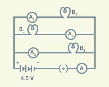
Solution:
(i) The glow of the bulbs
B2 and B3 will remain the same because glow of
bulbs depends on power. Power is given as
The potential difference (V) and
resistance (R) of B2 and B3
remain the same. Therefore, there will be no change in the glow of b.
(ii) The amount of
current flowing through each of the bulbs remain the same as the current, .
Both V and R in this case remains the same.
(iii) The net resistance
(R') of the three resistors connected
in parallel can be found from the following equations.
as
Therefore,
Long Answer Questions
Question 29
Three incandescent
bulbs of 100 W each are connected in series in an electric circuit. In another
circuit another set of three bulbs of the same wattage are connected in
parallel to the same source.
(a) Will the bulb
in the two circuits glow with the same brightness?
Justify your
answer.
(b) Now let one bulb in
both the circuits get fused. Will the rest of the bulbs continue to glow in
each circuit? Give reason.
Solution:
(a) No. The combined resistance
of the bulbs in series will be three times the resistance of the bulbs
connected in parallel. Therefore, the current in the series combination will be
one-third of the current in each bulb in the parallel combination. Therefore,
the bulbs in the parallel connections will glow brighter.
(b) When one of the bulbs
in both the connections gets fused:
·
The remaining bulbs
connected in the series stop glowing as the circuit is broken.
·
There will be no impact
on the two bulbs as the circuits for these bulbs remain intact without any
change in the voltage and the amount of current flowing through the circuits.
Question 30
State Ohm’s law?
How can it be verified experimentally? Does it hold good under all conditions?
Comment.
Solution:
Ohm’s law states that the potential
difference across the ends of a resistor is directly proportional to the
current passing through the resistor provided its temperature remains the same.
If I is the current flowing through a
conductor, and V is the potential
difference at its ends, then
where R
is the constant of proportionality and commonly called the resistance of a
conductor.
Experiment to verify Ohm’s Law:
Steps:
a)
We can set up a circuit
as shown in the figure. The circuit consists of a nichrome wire of length, say 1
m, an ammeter, a voltmeter and four cells of 2.5 V each.
b)
We will use only one cell
as the source in the circuit. We will note down the reading in the ammeter and the
voltmeter for the potential difference across the nichrome wire in the circuit
and tabulate these values.
c)
Next, we will connect two
cells in the circuit and note the respective readings of the ammeter and
voltmeter.
d)
We will repeat the above
steps using three cells and then four cells in the circuit, separately.
e)
From the table, we can
calculate the value of the V and I for each observation.
|
S.No
|
Number of cells used in the circuit
|
Current through the nichrome wire, I (ampere)
|
Potential difference across the
nichrome wire, V (volt)
|
( )
|
|
1
2
3
4
|
1
2
3
4
|
|
|
|
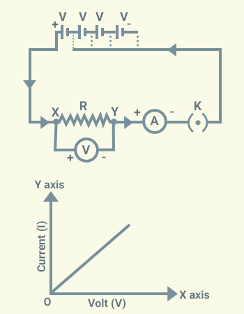
f)
We will then plot a graph
between V and I by taking V along X-axis.
Observation:
The VI graph is a
straight line that passes through the origin of the graph.
Conclusion- is a constant ratio. This verifies Ohm’s Law.
This law does not hold
good for all situations. For example:
·
This law is valid only
for conductors, provided the temperature and other physical conditions remain
constant.
·
It is not followed in
case of insulators.
Question 31
What is electrical
resistivity of a material? What is its unit?
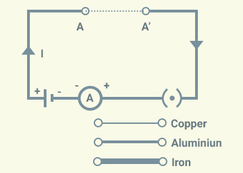
Describe an
experiment to study the factors on which the resistance of conducting wire
depends.
Solution:
Resistivity is numerically equal to the resistance of a wire which is 1 metre
long having a cross section of 1 square metre.
In simple words, the more is the resistivity of a substance, the more is
its resistance per unit length and per unit area.
The SI unit of
electrical resistivity is ohm-metre (Ωm).
Factors that affect the resistance of a
wire:
a)
Material (resistivity)
b)
Cross- sectional area
c)
Length
d)
Temperature
Experiments:
a)
Let us take wires of different materials like copper, aluminium, iron of same
cross-sectional
area and of the same length.
b)
Let us connect to a circuit as shown in the figure. Here AA’ represents a wire.
(i) Let us connect each wire one by one
between A and A’. After that, let us insert
the key into the plug and note down the
reading of the ammeter.
Observation:
The value of the current is different for different wires.
Conclusion:
Since the same cell is used every time, the potential difference (V) across the wires is same. This means different
wires used in this experiment draw different currents when the same potential difference
is applied across them.
Hence, R α ρ
(ii) Let’s perform the same activity as
done earlier by taking the same wire of different cross sections.
Observation:
The value of the current is different for different cross sections of the same
wire. The more is the cross section, the more is the current flowing through
the wire.
Conclusion:
Resistance is inversely proportional to the area of cross-section (A)
(iii)
Let’s perform the same activity as done before by taking the same wire of
different lengths.
Observation:
As the length increases, the current in the circuit decreases.
Conclusion: The
resistance is proportional to length.
(iv) Finally, let’s perform the same experiment
by increasing the temperature of the lab where the experiment is being
performed.
Observation: The higher the temperature, the
lesser is the current.
Conclusion:
The higher the temperature, the higher is the resistance.
Question 32
How will you infer
with the help of an experiment that the same current flows through every part
of the circuit containing three resistances in series connected to a battery?
Solution:
We can use three bulbs as resistors to
perform this activity. We can make the connections as shown.
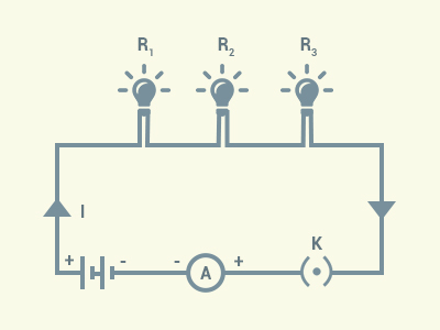
We will take readings of the ammeter by
positioning it before the resistor ,
after the resistor ,
between .
Observation:
The ammeter reading for the given setup remains the same for every position.
Conclusion: The
same current flows through every part of the circuit containing three resistances
in series.
Question 33
How will you
conclude that the same potential difference (voltage) exists across three
resistors connected in a parallel arrangement to a battery?
Solution:
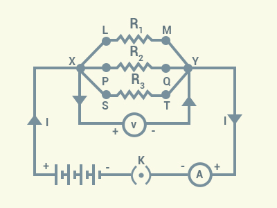
This
can be proved by a very simple logic. Let us take a parallel connection of
three resistors are shown. The potential difference across the resistor R1 is same as the difference
in the electric potential between the point X and Y.
Similarly,
the potential difference across the resistors are
same as the difference in the electric potential between the points X and Y.
Thus, we can conclude that the same potential
difference (voltage) exists across the three resistors connected in a parallel
arrangement to a battery.
Question 34
What is Joule’s
heating effect? List its four applications in daily life.
Solution:
The heating of resistor because of
dissipation of electrical energy is commonly known as “Heating Effect of
Electric Current”. The heat lost in the process is explained by the Joule’s Law
of Heating. The law states that the heat produced in a resistor is:
(i) Directly proportional to the square of
current for a given resistance
(ii) Directly proportional to resistance
for a given current, and
(iii) Directly proportional
to the time for which the current flows through the resistor.
Four applications of Joule’s law of heating
are:
a)
Electrical appliances
such as electric iron, electric toaster, etc.
b)
Filaments of the electric
bulbs,
c)
Utilised in electric fuse
for protection of household wiring and electric appliances,
d)
Electric heater, room
heater, geyser, etc.
Question 35
Find out the
following in the electric circuit given in following figure.
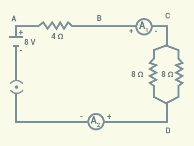
(a) Effective
resistance of two 8 Ω resistors in the combination
(b) Current
flowing through 4 Ω resistor
(c) Potential
difference across 4 Ω resistance
(d) Power
dissipated in 4 Ω resistor
(e) Difference in
ammeter readings, if any
Solution:
(a) The two given
resistors of 8 Ω each are connected in parallel.
For 2 resistors connected in parallel, the
effective resistance R is given by:
(b) The current (I) flowing through the 4Ω resistor .
(c) The potential difference across the 4 Ω
resistor .
(d) The power dissipated in 4 Ω resistor .
(e) Both the ammeters will show the same
current reading as the same current
passes through each of these.